Voice Interface – Pi Hub-Vox

I am using a Pi 3 Model B with the Voice Hat attached, and assembled as per the instructions provided in the MagPi magazine. Internet access is required, if you want to use the Google service or other cloud offering for Speech-To-Text and obviously network access is required to make REST calls to our home-hub.

The published AIY design requires the big green button to be pushed (or a hand clap) to activate listening mode. Most users want a wake-word as in Alexa, OK Google, Hey Siri, etc.  I was attracted by the Snowboy Hotword Detection Engine, and have recorded a hotword for my system. I still use the green led as a listening indicator.

The listening mode is a contentious subject. On the one hand we do not want voice assistants streaming all our conversations to the cloud, however, with a dedicated voice appliance like the hub-vox, repeatedly issuing wake commands becomes tedious.  Snowboy, being a local detector, provides us with control over this balancing act.

A warning that there is a lot of software that requires installing for the hub-vox, but a script has been written which will complete the task based on a plain vanilla Raspbian Stretch Lite operating system. If you want to install each component separately, you can copy and paste commands from the script to the command line.

Fetch the script…

wget http://www.warrensoft.co.uk/home-hub/linuxscripts/vox/setup.sh

edit the script to customise the settings…

nano setup.sh

make the script executable…

sudo chmod +x setup.sh

and then run it…

sudo ./setup.sh

Here is a summary of the main components installed:

  • Samba – for managing our code
  • Vox code – from the project repository
  • Voice Hat drivers – for microphones and speaker
  • Snowboy – hotword detection
  • PyAudio
  • Python Speech Recognition
  • Google api python client – STT
  • Flac, Pico2wave, Sox – TTS

In the next post we will assemble a test list of utterances and pipe that through the Phrase Processor.

Electronics – Connecting a Sensor

Simulated sensors are fine for testing, and they could be used to configure and check most of the features of the hub, however nothing compares to making real measurements!

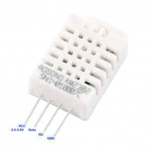
Here is the pin-out of the AM2302 sensor, which is widely available:

We can connect the VCC pin directly to the pi’s 3V3 pin, the GND pin to Pi Ground and the Data pin to any of the GPIO input pins.  This is the main benefit of this sensor model, the fact that we can cover a lot of zones with just the pi’s on-board i/o capabilities.

The cable required is not critical, and I have employed cheap 6-core burglar alarm cable. I have also experimented with cat-5 twisted core network cable and it does not provide any gains. As mentioned in a previous post, there is a limit to the distance between the pi and sensor, for this configuration to work. Adding a 1k resistor between the Data pin and VCC pin, at the sensor end, extends this distance to approximately 4m, but this may vary depending on the particular installation. If this is a serious constraint, then I would recommend the alternative BME280 sensor.

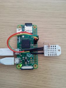
For test purposes I use a simple desktop setup. Here is a picture of my development server, based on a pi zero.

Now we have our sensor hardware sorted we need to configure the software.

Hardware – Sensors

The majority of measurements in the production version of the home hub utilised the DHT22/AM2302 temperature and humidity sensor.

DHT22/AM2302

The DHT22, AM2302  or equivalent has a number of benefits:

  • low cost
  • single-wire bus connection
  • interface software readily availableThe only drawback I have come across is the limitation of cable distance. In practice, even with corrective measures, the maximum distance from Pi to sensor is about 4m.
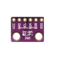
BME280

For this reason I have deployed the BME280 in situations where greater distances are involved. Fortunately the production version was installed in a bungalow, which permitted the majority of rooms to be reached using short cable runs from the centrally loft-mounted pi.

Unfortunately, the BME280 sensor requires additional circuitry to connect the Pi to its I2C or SPI interface. I will cover this in a later post.

Hardware – Relays

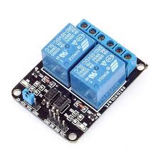
I have found these common relay modules to be suitable for the control outputs for the home hub, where switching of mains voltages is required. They feature optical isolation, are low cost, come in single, dual and multiple packages and are readily available from a number of suppliers. There are many tutorials on the web if you require further information on interfacing, but do take care when working with mains electricity, and consult a qualified electrician if in any doubt.

Hardware – the Pi

The production version of the home hub is running on a Raspberry Pi 2 with 1 GB of ram. The 4 cores and extra ram is helpful to run the PostgreSQL database, but it is probably possible to run the hub on a lower specification Pi. I have employed Ethernet networking, to connect to my home network, as wi-fi has not proved sufficiently reliable in my set-up. The usual caveats about using a properly sized power supply are particularly relevant for this project, as you may be providing power for additional sensors and relays.