
A simple switch connected between a spare GPIO pin and ground will be sufficient to test impulses, however, in real life it will likely prove to be very unreliable. Depending on the length of the wires, and the amount of electrical noise in the locality you can expect false triggers.
The code uses the RPi.GPIO library’s event detection facility, to register a callback function which is invoked when a button is pressed. The feature has a debounce parameter, however it can be difficult to set this to the optimum value.
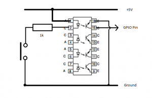
The solution is to add an opto-coupler such as the ILQ74 quad package. The led input side is fed from the pi’s 5V supply, through the switch and a 1k resistor to ground, and the output transistor connects the GPIO input pin to ground. The principal here is that a much larger current is required to light the led and trigger the input. Extraneous noise will be insufficient to trigger it.
Now we have the electronics sorted we can configure our impulse.