
Simulated sensors are fine for testing, and they could be used to configure and check most of the features of the hub, however nothing compares to making real measurements!
Here is the pin-out of the AM2302 sensor, which is widely available:
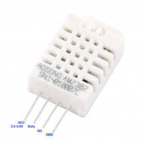
We can connect the VCC pin directly to the pi’s 3V3 pin, the GND pin to Pi Ground and the Data pin to any of the GPIO input pins. This is the main benefit of this sensor model, the fact that we can cover a lot of zones with just the pi’s on-board i/o capabilities.
The cable required is not critical, and I have employed cheap 6-core burglar alarm cable. I have also experimented with cat-5 twisted core network cable and it does not provide any gains. As mentioned in a previous post, there is a limit to the distance between the pi and sensor, for this configuration to work. Adding a 1k resistor between the Data pin and VCC pin, at the sensor end, extends this distance to approximately 4m, but this may vary depending on the particular installation. If this is a serious constraint, then I would recommend the alternative BME280 sensor.
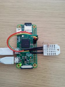
For test purposes I use a simple desktop setup. Here is a picture of my development server, based on a pi zero.
Now we have our sensor hardware sorted we need to configure the software.