Controller – BME280 Sensor

This is the most challenging phase of the hub project – implementing the BME280 Sensor. This sensor is an amazing piece of electronics: providing temperature, humidity and pressure measurements all for under £10. There is one small snag however; the sensor comes with I2C and SPI interfaces which are designed for very short distance communications e.g. where the sensor is mounted on the same pcb as the controlling processor.  This conflicts with our requirement to have sensors many metres from the controlling Pi.

The Pi has I2C and SPI interfaces, so we might be tempted to use a pi zero as a slave bridge, but this is slight overkill and would be a software maintenance overhead.

All is not lost however. The Pi also has a a serial interface, and this is much more suitable for transmission over long distances, especially if we can operate at low baud rates. So all we require is a serial to SPI converter. A quick trawl of the electronics catalogues didn’t throw up any suitable candidates, so I decided to make one with a PICAXE programmable chip. Once you overcome the apprehension of working with yet another programming language (the PICAXE is programmed in a proprietary form of BASIC), the implementation is straightforward. The setup has been working flawlessly in my installation for many months.

You can download the PICAXE program from here.

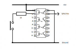
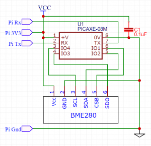
I used the smallest of the PICAXE family – the PICAXE-08M2. This is an 8-pin device, which after power and serial tx/rx leaves 4 pins to use for the custom SPI interface. Some of the larger devices have SPI capability built in, but in the interest of economy this design uses software.  Here is the circuit diagram:

You will need a prototyping board and download cable in order to transfer the program to the picaxe chip, but these are very reasonable and can be reused for other projects. The circuit can be built on veroboard, or alternatively, you can find details of a custom PCB here:

https://easyeda.com/paul.warren/BME280_Serial_To_SPI_Adapter-0666de5ee88f4876baacad8906b33be8

I would recommend using sockets for the picaxe chip and the sensor, as lightning-strike damage is not unheard of.

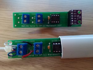
I was fortunate to have a redundant overflow pipe in my property, which served as a convenient conduit for exposing the sensor to the external environment.

In the next post we will install the Sensor Helper.

Controller – Meteorology Installation


There are a couple of prerequisites that we need:

sudo pip install python-dateutil

sudo apt-get install python-lxml

If you get an error installing dateutil, try again after removing and replacing pip :

sudo apt-get remove python-pip
sudo easy_install pip

Then we can fetch the sensor helper:

wget -P /usr/local/bin/code/controller/sensor_helpers http://www.warrensoft.co.uk/home-hub/code/controller/sensor_helpers/meteorology.py

uncomment the meteorology sensor in /sensor_helpers/__init__.py

and restart the controller.

Add a new sensor via the Organisation option of the website, and populate the SensorFunction as discussed previously. When displayed in Current Values the reading will be time-stamped with the applicable time:

The meteorology facilities give you a wide range of possibilities for implementing intelligent control algorithms within your hub. Next we will look at an alternative hardware sensor.

Controller – Meteorology Registration

You can register for a UK Met Office DataPoint account here.

Once registered you will be allocated an Application Key, which is required for all queries. In addition to your application key, you will need to know the location id for your nearest monitoring site. A list of locations can be obtained by running the following query in a browser:

http://datapoint.metoffice.gov.uk/public/data/val/wxfcs/all/datatype/sitelist?key=<APIkey>

xml response


It is a long list so you may have to search it to find the nearest location, or use your latitude/longitude coordinates. Once you have your location id, you need to populate 2 new hub user settings: DataPointKey and DataPointLocation.  You can add these in the Organisation page of the website, or use the following commands updated with your own <values>:

 psql -U postgres -d hub -h localhost -c 'INSERT INTO "UserSetting"("Name", "Value") VALUES ('"'"'DataPointKey'"'"', '"'"'<APIkey>'"'"');'
 psql -U postgres -d hub -h localhost -c 'INSERT INTO "UserSetting"("Name", "Value") VALUES ('"'"'DataPointLocation'"'"', <LocationID>);'

We are now in a position to get the forecasts for our location. Plug your values into the following query:

http://datapoint.metoffice.gov.uk/public/data/val/wxfcs/all/xml/3840?res=3hourly&key=<APIkey>

xml response


If you inspect this xml response you will see the list of available parameters. What we require is the parameter name  e.g. ‘G’ is Wind Gust, ‘Pp’ Precipitation Probability, etc. This is a good time to add any new Measurands to our hub organisation.

We should now have all the information we require to populate the SensorFunction field of a new sensor:

e.g. meteorology.240.S

this translates to a look-ahead timespan of 4 hours and the Wind Speed parameter. The hub code will find the nearest forecast to our requested time, and read the data. The reading will be time-stamped with the future time.

Read on to complete the software installation.

Controller – Meteorology Overview

If you live in the UK then you have access to the excellent Met Office DataPoint service. To quote their website:

DataPoint is a service to access freely available Met Office data feeds in a format that is suitable for application developers. It is aimed at anyone looking to re-use Met Office data within their own innovative applications, for example professionals, the scientific community, student and amateur developers.

The hub meteorology sensor type allows us to use met office readings as if they were connected sensors.  This saves us implementing our own physical sensor, which might not be practical, and also gives us access to forecast data without requiring our own super-computer!  For example, if we wanted to know the predicted local temperature, to turn on heating in advance , we can use this facility.

In my opinion this is what elevates the Raspberry Pi to super stardom – the symbiotic combination of global data and local control.

In order to use the service you need to register, but it is free. Once registered you will be allocated an Application Key, which is required for all queries. In addition to your application key, you need to know the location id for your nearest monitoring site and the name code of the parameter you want to measure. Here is a checklist of the required tasks:

  1. Register for a DataPoint Account
  2. Collect your Application Key
  3. Use Key in browser query to obtain a list of sites
  4. Find your nearest site in list – note location id
  5. Populate hub user settings for application key and location id
  6. Use Key in browser query to obtain a list of parameters for that site
  7. Look up the parameter name code for measurement you require
  8. Calculate the look-ahead timespan in minutes e.g. 0, 180, 360, etc.
  9. Assemble your sensor function from the look-ahead and parameter name
  10. Install prerequisites for python
  11. Install the meteorology sensor helper from project repository
  12. Restart Controller
  13. Configure new sensor with sensor function


In the next post I will provide sample browser queries required to set things up.

Controller – Slave Hub

You will have seen references to the slave flag in the main scheduler program. This is a boolean value passed in when the controller is first started up. We have set it to false for all operations to date, as we have been building our master hub, but if we set this flag to true then we would launch the hub in slave mode.

A Slave hub is a cut-down appliance that is focused on reading sensors and driving actuators. It still has all of the software installation of a master hub, but some routines are not used. I will be publishing an installation script and SD image file in the resources section soon, so you don’t have to manually construct another hub. The master hub will talk to the slave over the network, giving you the extended reach for your sensors and actuators. The Pi Zero W is the ideal candidate for implementing a slave hub.

Once you have your second pi up and running, all that is required to make it a slave is the following:

1. Install the api:

wget -P /var/www/html http://www.warrensoft.co.uk/home-hub/code/website/html/api.php

2. Change the slave hostname – to distinguish master and slave when configuring

3. Edit /etc/rc.local and change the –slave=false to –slave=true in the line launching main_sched.py and optionally reduce the logging level to just errors –log=ERROR or no logging –log=CRITICAL

4. Reboot the slave

5. Test the api:

http://slave-hub/api.php?sensor=1

Now we need to add some software to our master hub to equip it to talk to slaves.  This comes in the form of a remote sensor helper and a remote actuator helper.

wget -nH -x --cut-dirs=3 -P /usr/local/bin/code/controller/ -i /usr/local/bin/code/controller/manifest5.txt http://www.warrensoft.co.uk/home-hub/manifests/controller/manifest5.txt

These helpers need to be un-commented in their respective __init__.py files.

We also need the python requests module, via pip:

sudo apt-get install python-pip
sudo pip install requests
sudo pip install --upgrade requests-cache

Restart the controller and add a new sensor, this time with the Sensor Function of the form:

remote.x.y

where x represents the least significant part of the ip address of the slave, and y represents the remote sensor number. For example, if we had a master hub on 170.30.90.40, and a slave on 170.30.90.41 with a Sensor S3,  then the sensor function in the master would be:

remote.41.3

Once configured the remote sensor is identical to a local sensor, and can be sampled, alerted, monitored, etc.

An identical  approach applies to remote actuators, so the actuator function remote.41.4 would control actuator 4 on the slave hub.

Just a note about security. Remote access to the api page is not secure, unlike the normal website functions. Rather than publish details on a public blog, it is left to the reader to implement whatever mechanism they feel is appropriate. One possible setup is to make just the master hub website accessible over the internet, on a different port, but not the slave hub(s). Consult your router documentation for details.

Next we will look at fetching our readings from slightly further afield.

Home Hub Sensors – Next Steps

Having completed all the milestones in the project plan, you should have a functioning home hub, with the knowledge to customise and configure it to meet your own requirements.

What I would like to do now is consider some more advanced topics and modules that will greatly add to the value of the hub. The first area to consider is sensors. We have deployed the AM2302 family successfully, but there is a limitation in terms of cable distance.  This could be a showstopper, preventing the hub design from being usable in your property. I want to describe three solutions, each being applicable to progressively longer distances between hub and sensor, and each having advantages and disadvantages. Here is a table which enables the comparison:

Sensor Type Max Distance Feature Summary
AM2302 Family4-5m* Cheap
* Single Pin
BME28010-15m* Cheap
* Complex electronics
* Pi only has 1 serial port
Slave Hub15-25m* Cheap
* Complex configuration
Remote Meteorology10-100km* Free
* Not locally representative

From this table you will be able to determine which approach best meets your requirements.

Having this design operational in my house for a number of months I have learnt some lessons. The Raspberry Pi is a fantastic device for hosting this application, but its Achilles heel is the SD card. Perhaps it’s the number of writes being made by the database and the logging. For this reason I added a USB hard disk to my master hub and the reliability has greatly increased. I followed this excellent walk through.

First up, I will describe the Slave Hub solution, as this builds on the work already done.

Controller – Statistics

Now we are collecting data on a regular basis it would be a shame not to record some simple statistics, maximum and minimum values, for each of our measurements. This is what the controller statistics module does.

Download the python script…

wget -P /usr/local/bin/code/controller http://www.warrensoft.co.uk/home-hub/code/controller/statistics.py

and uncomment lines 22, 195 and line 206 of main_sched.py to enable the statistics features. Restart the controller.

A summary of the highs and lows appears, not surprisingly, on the Statistics page. In addition, a daily summary of changes can be delivered by email.

There are a couple of User Settings we need to take care of to complete the configuration. First, there is the Admin Recipient: this is the email address of the occupant who will receive the daily summary report, and secondly Summary Enabled needs to be set to true.

With the configuration completed,  a report will be sent detailing any new highs and lows for the day to the admin user.

From:
Date: 9 Jun 2017 01:00
Subject: Daily Highs and Lows from the Hub 2017-06-09
To: user@example.com
Cc:

 The following highest values have been recorded today:

 * Test Temperature 33.6 degrees C at 23:25 08/06/2017
 * Sinewave Angle 1.0 units at 23:15 08/06/2017

 The following lowest values have been recorded today:

 * Test Temperature 20.5 degrees C at 00:00 09/06/2017
 * Sinewave Angle -1.0 units at 23:45 08/06/2017

Not all sensor readings generate meaningful statistics, so the feature can be disabled on the Sensor form. Be aware that disabling a sensor’s statistics will delete any history.

With statistics implemented we have completed all the milestones in the project plan. In the next post we will reflect on what we have achieved, and consider the next steps.

Website – Impulses

We already have the facilities to add and edit impulses, within the Organisation menu option.  Select the Add Impulse link and fill in the details. The key field is the BCM Pin. This obviously needs to be the pin that your switch is connected to. The controller is constantly monitoring impulse configurations in the database, in order to set up the necessary event callback hooks.

The next step is to monitor the event queue on the website Statistics page, while pressing the impulse button. As mentioned earlier, debouncing may not be sufficient defence against noise, so the controller code employs an additional lockout mechanism which prevents repeat events within 10 seconds of a button press. The main scheduler module is already optimised to keep a lookout for rules, and to process actuators, so the overall effect is that there should be reasonable response to pressing an impulse button.

The event queue is the place to track impulse events and make sure you are getting the expected results. As with Conditions, Impulses won’t be processed until there is a connected Rule and Action. Make sure you use the toggle_actuator Action Function for impulses, to get the push-on-push-off behaviour, unlike the action_actuator used previously for Conditions.

Impulses will appear as a clickable icon on the Current Values page of the website, within the Zone of their linked Actuator.

There is only one topic left on our project plan to implement – Statistics. This is covered in the next post.

Impulse Electronics

A simple switch connected between a spare GPIO pin and ground will be sufficient to test impulses, however, in real life it will likely prove to be very unreliable. Depending on the length of the wires, and the amount of electrical noise in the locality you can expect false triggers.

The code uses the RPi.GPIO library’s event detection facility, to register a callback function which is invoked when a button is pressed. The feature has a debounce parameter, however it can be difficult to set this to the optimum value.

The solution is to add an opto-coupler such as the ILQ74 quad package. The led input side is fed from the pi’s 5V supply, through the switch and a 1k resistor to ground, and the output transistor connects the GPIO input pin to ground.  The principal here is that a much larger current is required to light the led and trigger the input. Extraneous noise will be insufficient to trigger it.

Now we have the electronics sorted we can configure our impulse.

Impulses

Impulses provide the last of the three key interaction modes we require:

¤ Automated
¤ Remote
¤ Interactive

The mobile-friendly website is fantastic for keeping tabs on your home while you are absent, and could be used within the home, but it can be slightly irksome to have to login to a website just to turn on the heating. This is where the Impulse comes to the rescue. It is a simple button, connected to the hub, which with suitable configuration can generate events much like Conditions.

The concept is very topical, with the release of the Amazon dash buttons (details for connecting these to the hub are provided in a later post!).

Use the following command to download the controller code for impulses:

wget -P /usr/local/bin/code/controller http://www.warrensoft.co.uk/home-hub/code/controller/impulses.py

Uncomment the code for impulses in lines 35 and 186 in main_sched.py, and restart the controller.

Next we need hook up a button to our pi, so we can trigger the impulse. This is discussed in the next post.